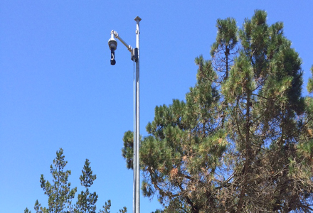
The use by MDOT of 90-foot concrete poles on which to mount CCTV equipment reduces the number of poles needed to monitor a given area and incidences of occlusion
HNTB is working with theThe design includes a 12-mile VII testbed, closed circuit television (CCTV) cameras, dynamic message signs, vehicle detectors, towers and communications wireless links to extend coverage over 75 miles of interstate, including the approaches to the Blue Water Bridge in Port Huron. The project also includes a complete replacement of legacy network equipment, including the transition from analogue to digital video. This equipment is nearing end-of-life after approximately 15 years of operations and is becoming an increasingly costly maintenance issue for MDOT. Along with the new roadside equipment, including poles, cameras and vehicle detection, the entire core network contained in five communications hubs will be upgraded from the legacy Sonet system to a 10Gb native Ethernet system. The entire project is expected to take two years and be completed by spring 2008.
Pole manufacture and installation
The camera poles for this project are spun concrete with a density of 8,000 to 10,000psi to impede the absorption and migration of water. The poles are created with a centrifugal process that starts with a 'cage' or frame, consisting of a cylinder of high-strength steel strands. The frame is laid lengthwise inside a mould. High-density concrete is dispensed into the mould and roughly packed on the frame. The mould is locked into place and then spun at a high speed, sending the concrete to the sides while filling all voids around the frame. The steel of the cage is stressed by pulling on it. The spun concrete forms a hollow pole and is cured by sending low-pressure steam through the centre. The tension is then removed from the steel. The poles will be 90 feet tall from the ground to the top, with another 15 feet buried in the ground. A concrete skirt poured around the pole base creates additional stability to the pole. This direct burial is another cost saver for the project, as it eliminates the need for an anchor system, making for quicker and easier installation.The VII portion of this project consists of a nine-mile stretch of I-96 from I-675 to the Livingston County line. HNTB has designed the VII equipment to be installed every third of a mile with a tie-in to the backbone access points once every mile. With the exception of the locations that need to communicate to radio aggregation points, most equipment is to be mounted at light pole height. The design will tie into the Michigan Intelligent Transportation Systems (MITS) backbone and this stretch of VII testbed will be used as a field operational test.
Improved coverage
The most noticeable element of the project is the towering poles equipped with CCTV cameras that are being installed along the roadway (see Sidebar). When an incident occurs on the roadway, information regarding location, severity and traffic queues is crucial to the recovery process. It is in these situations that an unobstructed view and clear images are necessary to facilitate the rapid deployment of emergency personnel, bringing aid to those affected and quickly clearing the roadway and returning traffic flows to normal.There are a number of reasons why HNTB decided to use higher poles for this project. The first is the reduction of possible occlusions by existing structures, roadway vegetation and taller vehicles travelling in the lane closest to the camera. By using taller poles for the project, the camera can obtain a wider field of view as well as see over tall objects. The height also allows for a picture that excludes the horizon and any attendant glare. The detection of gapping - the space between the front of one vehicle and the rear of the next - is also more accurate with increased camera height. Added height also has a direct effect on the total number of poles needed to cover an area - with the extended fields of view afforded by greater height, cameras can be placed further apart and the number of poles needed can be reduced. This particular project requires 34 poles that are 90 feet tall. For comparison, were 50-foot poles to be used, around 50 would be needed to provide coverage of the same area.
Maintenance savings
Fewer poles also means that fewer power drops are needed - the biggest lesson learned in past Michigan roadway projects is that power drops are a major expense and are almost always underestimated, according to David Jones, deputy project manager.Jones adds that the cost savings brought about by having fewer power drops and the reduced number of poles more than make up for the use of the taller and more expensive poles.
Maintenance of the cameras is made easier and safer with the use of camera lowering devices. The dome cameras are mounted with a pulley system installed within the camera pole itself that allow the cameras be lowered to the ground, eliminating the need for bucket trucks/cherry pickers. The use of bucket trucks creates the need for Maintenance of Traffic (MOT) even if only the shoulder is being closed. Camera lowering devices are very popular with State DOTs due to the added coverage the higher mounting height yields and the lack of MOT required during the maintenance of the CCTV cameras.
Picture quality
The cameras selected by the contractor for the project areThe value of wireless This project will utilise wireless technology for communication between instruments. The data cables inside the poles allow for the transfer of video information to the control cabinet at the base of the pole, which encodes the video to MPEG4 format before it is wirelessly transmitted to the network. The line of sight for wireless devices is clear when mounted above traffic and other physical barriers. Using wireless devices also saves the cost of installing optic-fibre cable into and between the device sites. The wireless antennae installed for the cameras are a point-to-multipoint link, directing the information to five communication towers. The towers wirelessly communicate via a point-to-point link to the MDOT hubs and then the network.


